
KAYOU Engineering Guide
Cantilever Racking Load Capacity Guide: How to Size Arms, Uprights and Bays for Long Materials
What Does Cantilever Racking Load Capacity Mean?
“Load capacity” can refer to several different limits. They must not be used interchangeably.
| Capacity term | What it means | What must be confirmed |
|---|---|---|
| Arm capacity | Maximum approved load carried by one arm under a defined load position | Arm length, profile, connection, load centre and restraint |
| Upright capacity | Load that one column assembly can support | Number and spacing of levels, loads on each side, column height, bracing and base |
| Bay capacity | Capacity assigned to a defined section in the project drawing | Exact meaning of “bay,” column spacing and supported load arrangement |
| System capacity | Capacity of the complete installed rack | All components, anchors, floor, load combinations and site conditions |
The current US industry document is ANSI MH16.3-2025, Design, Testing, and Utilization of Industrial Steel Cantilevered Storage Racks. Destination-market, building-code and seismic requirements may add further obligations.
Step 1: Define the Long Material Before Selecting the Rack
Sizing starts with the load. For every product or bundle, record:
Maximum weight, length, depth and height
Whether the weight is uniform or concentrated
Product stiffness and acceptable sag between supports
Bundle straps, fork-entry positions, lifting method and permitted overhang
Risk of round items rolling or loose pieces shifting
Number of bundles stored on each level
Equal-weight bundles can impose different forces. A rigid timber pack may distribute weight across several arms, while flexible tubing can place more weight on selected supports. Loads near an arm tip also create more bending than loads closer to the upright.
Step 2: Estimate the Reaction on Each Arm
For a rigid, uniformly loaded bundle resting evenly on identical supports, a useful preliminary estimate is:
Average reaction per support = total bundle weight ÷ number of effective supporting arms
Worked Example
A 2,400 kg bundle is intended to rest on four arm lines:
2,400 kg ÷ 4 = 600 kg average reaction per arm
This does not prove that a 600 kg arm is adequate. The final design must check the worst reaction, uneven loading, overhang, load centre, connection and applicable load combinations. Flexible material may not produce equal reactions, so a qualified rack designer must approve the basis.
Do not add an arbitrary “safety factor” to an undefined catalogue value. The supplier should state whether a capacity is a working load, allowable load, test result or ultimate value.
Step 3: Size Arm Length, Profile and Load Centre
Arm length should suit load depth. Excess length moves the load centre outward and increases bending; insufficient length can leave the bundle unsupported.
Ask the supplier to show these items on the approved drawing:
Usable arm length and overall arm length
Maximum permitted load and its load centre
Arm profile, steel grade, thickness and connection
Straight or inclined configuration
End-stop type and height, where required
RMI guidance on cantilever arm depth emphasizes matching the arm to the stored load. End stops can help reduce roll-off risk, but they are not a reason to overload a rack and should not be treated as the primary restraint for unstable goods.
Step 4: Determine Upright Capacity
An upright receives reactions from every loaded level plus bending and lateral effects. Adding arm reactions gives only a preliminary gravity total; final selection must also consider:
Vertical position and spacing of every arm level
Single-sided or double-sided loading
Unequal loading between the two sides
Column height and unbraced length
Base, anchors, floor, horizontal forces, impact and seismic conditions
Bracing configuration and connection details
A double-sided upright cannot automatically carry the full one-sided rating on both sides; combined and unbalanced cases must be checked. Do not rely on a wall for stability unless the connection and building are designed for it.
Step 5: Choose Column Spacing and the Number of Supports
Column spacing controls the material span. Excess spacing can cause sag, damage or instability even when every arm is below capacity. Additional supports reduce span but affect access and cost.
There is no universal support-spacing rule. Product stiffness, bundle construction, allowable deflection, overhang and lifting method all matter.
For flexible products, provide material properties or maximum permitted sag. Supports should avoid bundle straps and fork entries. Check every stock length; a layout for long stock may not support shorter bundles correctly.
Step 6: Define the Bay and Total Rack Load Clearly
“Bay” may mean the space between columns, one arm line or a starter/add-on section. A statement such as “5 tonnes per bay” is therefore incomplete without a drawing.
The capacity document should identify:
Number and centre-to-centre spacing of columns
Arms per level and number of levels
Maximum load per arm, defined bay and upright
Approved load dimensions and load centre
One-sided and two-sided loading conditions
Base, bracing, anchor, floor and site assumptions
Multiplying arm capacity by the number of arms is not a valid way to establish system capacity. The upright, base, bracing, anchors or slab may govern first.
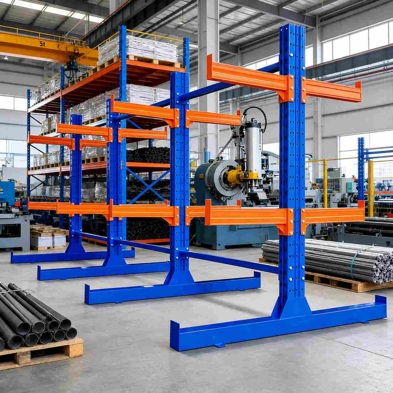
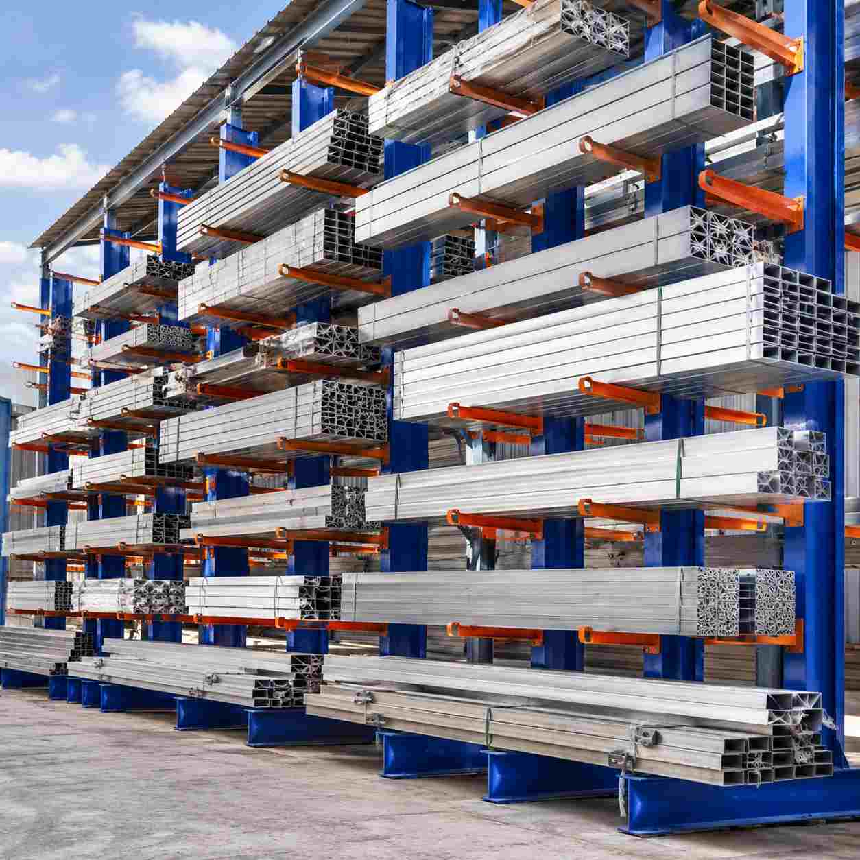
Single-Sided vs Double-Sided Cantilever Racking
| Configuration | Best suited to | Key design concern |
|---|---|---|
| Single-sided | Perimeter storage and access from one aisle | Stability, base projection and anchorage under one-sided loading |
| Double-sided | Central rows with access from both aisles | Combined column load and unequal loading between sides |
The choice should follow the warehouse layout and handling flow. Double-sided racks improve space use in central rows, while single-sided racks can work well along a perimeter. Neither layout removes the need for adequate aisles, load clearance and impact protection.
What Evidence Should a Buyer Request?
A reliable manufacturer should connect each claim to the supplied structure. Request:
Project layout and load application drawings
Component drawings, bill of materials and material specifications
Engineering calculations or a model-specific test basis
Arm, upright and system capacity definitions
Base-plate, anchor and floor-load requirements
Assembly instructions and load-capacity plaques
Material, dimensional and weld records as applicable
Trial-assembly or pre-shipment inspection evidence
RMI explains that its updated certification applies to a complete, project-specific cantilever rack system, not blanket approval of one arm, upright or base. Even where certification is not required, verify the actual configuration, loads and site.
KAYOU can support drawing review, material verification and production inspection through its quality control process. Final documentation should match the approved model and order revision.
Installation, Load Plaques and Inspection
Capacity is valid only when the rack is installed as designed. Bases must be level; specified anchors, bracing and arm locks or bolts must be complete. Floor joints and edges near anchors require review.
Display the approved configuration and limits on a load plaque. Moving arms, adding levels or changing the loading arrangement requires reassessment.
Inspect routinely and after impacts for bent arms, permanent deflection, damaged stops, twisted columns, loose connections, cracked welds, anchor damage and corrosion. Isolate affected locations pending qualified evaluation. OSHA 29 CFR 1910.176(b) requires stored materials to be stable and secure against sliding or collapse.
RFQ Checklist for a Cantilever Rack Project
To receive a technically useful quotation, send KAYOU:
Warehouse drawing and clear height
Bundle dimensions, maximum weight, and shortest and longest stock
Quantity per level and required storage positions
Preferred one- or two-sided layout, levels and clearances
Forklift type, aisle width and handling direction
Environment, floor information and destination-market requirements
Photos of the material and current handling method
The KAYOU team can use these inputs to propose a suitable configuration within its warehouse racking systems range.
Frequently Asked Questions
Can total rack capacity be calculated by multiplying arm capacity?
No. That calculation ignores upright, base, bracing, anchor, floor and load-distribution limits. Use the lowest approved limit for the complete configuration.
How much should long material overhang the outside arms?
There is no universal value. Overhang must be checked against material stiffness, bundle stability, support spacing and handling clearance. Excessive or unequal overhang can change support reactions.
Can arm levels be moved after installation?
Only within an approved configuration. Changing level positions alters upright loading and unbraced lengths. Obtain written confirmation and update the load plaque where necessary.
Can components from different manufacturers be mixed?
Do not assume compatibility from appearance. RMI advises against mixing rack components unless the combination has been properly evaluated and approved.
Conclusion
Correct sizing starts with the material and its support behaviour. Arms must cover the worst reaction and load centre; uprights must cover every level and both sides; spacing must control sag; and bases, anchors, bracing and floor must work together.
Do not select a rack from one “kg per arm” number. A trustworthy proposal shows the support layout, structural load path and controlling approved drawing.
Plan Your Cantilever Racking System with KAYOU
Send us your material dimensions, maximum bundle weight, storage quantities, warehouse layout and loading method. KAYOU will review the application and prepare a project-specific configuration and quotation.